PIC16F887-I/P
8-bit PIC microcontrollers with 14KB flash, 368B RAM, and 40/44-pin packages
Manufacturer: microchip
series introduction
# PIC16F887 - I/P Product Series Introduction
## 1. Overview
The PIC16F887 - I/P is a highly versatile and widely - used microcontroller product series from Microchip Technology. These microcontrollers are part of the PIC16F family, which is well - known for its cost - effectiveness, low power consumption, and rich set of features. The "I/P" in the part number typically indicates the package type, often an 40 - pin PDIP (Plastic Dual In - Line Package), which is a common and easy - to - use package for prototyping and production.
## 2. Key Features
### 2.1 CPU and Memory
- **CPU Core**: The PIC16F887 - I/P is based on a high - performance RISC (Reduced Instruction Set Computing) CPU core. It has a Harvard architecture, which separates the program memory and data memory buses. This allows for simultaneous access to program instructions and data, resulting in faster execution speeds.
- **Program Memory**: It comes with 14 KB of Flash program memory. Flash memory is non - volatile, which means the program code stored in it is retained even when the power is turned off. This makes it suitable for applications where the program needs to be stored permanently.
- **Data Memory**: The microcontroller has 368 bytes of RAM (Random Access Memory) for storing variables and intermediate data during program execution. Additionally, it has 256 bytes of EEPROM (Electrically Erasable Programmable Read - Only Memory), which can be used to store non - volatile data such as calibration values or user settings.
### 2.2 Peripherals
#### 2.2.1 GPIO (General - Purpose Input/Output)
The PIC16F887 - I/P has a total of 33 general - purpose I/O pins. These pins can be configured as either inputs or outputs, allowing the microcontroller to interface with a wide variety of external devices such as sensors, actuators, and displays. The I/O pins can also be used for interrupt generation, which enables the microcontroller to respond quickly to external events.
#### 2.2.2 Timers/Counters
- **Timer0**: It is an 8 - bit timer/counter with an 8 - bit prescaler. Timer0 can be used for various timing applications, such as generating time delays, measuring time intervals, or as a simple counter for external events.
- **Timer1**: A 16 - bit timer/counter that can operate in either timer or counter mode. It can be used in applications that require more precise timing, such as real - time clock generation or pulse width measurement.
- **Timer2**: An 8 - bit timer/counter with a 16 - bit period register. Timer2 is often used in conjunction with the PWM (Pulse Width Modulation) module to generate PWM signals.
#### 2.2.3 PWM (Pulse Width Modulation)
The PIC16F887 - I/P has two independent PWM modules. PWM signals are commonly used for controlling the speed of motors, adjusting the brightness of LEDs, and other applications where the average power delivered to a load needs to be controlled. The PWM duty cycle can be adjusted from 0% to 100%, allowing for fine - grained control.
#### 2.2.4 ADC (Analog - to - Digital Converter)
It features a 10 - bit ADC with up to 13 input channels. The ADC can convert analog signals from sensors such as temperature sensors, light sensors, or potentiometers into digital values that can be processed by the microcontroller. This makes it suitable for applications that require analog signal acquisition and processing.
Images for reference
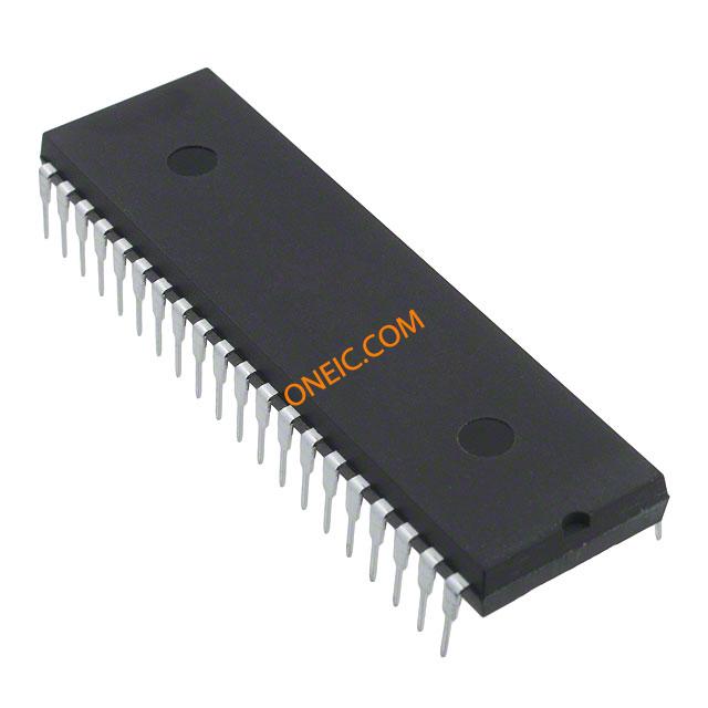
40-DIP

PIC18LF44K22-I/P

44-TQFP