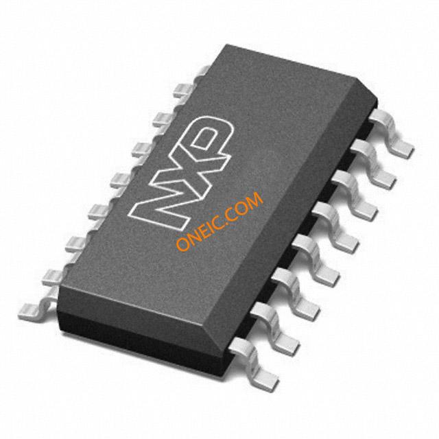
N74F161
4-bit synchronous binary counters in various 16-pin packages
Manufacturer: nxp
series introduction
# Introduction to the N74F161 Product Series
## 1. Overview
The N74F161 is a part of the 74F series of integrated circuits, which belongs to the high - speed TTL (Transistor - Transistor Logic) family. These integrated circuits are widely used in digital electronics for various applications due to their excellent performance characteristics. The N74F161 specifically is a 4 - bit synchronous binary counter.
## 2. Key Features
### 2.1 High - Speed Operation
One of the most prominent features of the N74F161 is its high - speed performance. The "F" in the 74F series stands for "Fast". It can operate at relatively high clock frequencies compared to some other TTL families. This high - speed operation makes it suitable for applications where quick counting and data processing are required, such as in high - speed communication systems, fast - paced digital control circuits, and high - frequency test equipment.
### 2.2 Synchronous Counting
The N74F161 is a synchronous counter. In a synchronous counter, all flip - flops are triggered simultaneously by the same clock signal. This ensures that the counting operation is well - coordinated and there are no propagation delays between different stages of the counter. As a result, the output transitions are clean and predictable, reducing the chances of glitches and errors in the counting sequence.
### 2.3 Parallel Load Capability
It has a parallel load feature. This means that the user can load a specific 4 - bit value into the counter in one clock cycle. The parallel load input (PL) is active - low. When PL is pulled low, the data present at the parallel data inputs (D0 - D3) is loaded into the counter on the next positive edge of the clock signal. This feature is useful for initializing the counter to a specific starting value or for re - setting the counter to a known state during operation.
### 2.4 Asynchronous Clear
The N74F161 is equipped with an asynchronous clear input (CLR). When this input is pulled low, the counter is immediately reset to its zero state (0000), regardless of the state of the clock signal or other inputs. This provides a quick and reliable way to reset the counter in case of an error or when a new counting sequence needs to be started.
### 2.5 Carry Output
The counter has a carry output (RCO). The RCO goes high when the counter reaches its maximum count value (1111 in binary). This output can be used to cascade multiple N74F161 counters to create larger - bit counters. For example, by connecting the RCO of one N74F161 to the enable input of another, a 8 - bit, 12 - bit, or even larger counter can be constructed.
## 3. Pin Configuration
### 3.1 Power and Ground
- **VCC**: This pin is connected to the positive power supply voltage. Typically, for TTL circuits, the power supply voltage is +5V. It provides the necessary electrical energy for the proper operation of the integrated circuit.
- **GND**: The ground pin is connected to the reference voltage level (0V). It completes the electrical circuit and provides a stable reference for all the internal components of the N74F161.
### 3.2 Inputs
- **CLK**: The clock input. The counter advances its count on the positive edge of the clock signal. The frequency of the clock signal determines the speed at which the counter counts.
- **PL (Parallel Load)**: As mentioned earlier, it is an active - low input. When low, it enables the parallel
Images for reference

16 SOIC

16-SOIC

16-DIP SOT38-1