CD74HC4514EN
High-speed CMOS 4-to-16 line decoder/demultiplexer with latches in 24-pin DIP package
Manufacturer: ['rochester', 'ti']
series introduction
# CD74HC4514EN Product Series Introduction
## 1. Overview
The CD74HC4514EN belongs to the 74HC series of high - speed CMOS logic integrated circuits. It is a 4 - to - 16 line decoder/demultiplexer with an inverting output. This device combines the high - speed operation characteristics of TTL logic with the low power consumption and high noise immunity of CMOS technology, making it a popular choice in a wide range of digital circuit applications.
## 2. Key Features
### Electrical Characteristics
- **Power Supply Range**: The CD74HC4514EN can operate within a power supply voltage range of 2V to 6V. This wide range provides flexibility in different power - supply scenarios, allowing it to be used in various electronic systems, from battery - powered devices to those with a standard 5V power source.
- **Low Power Consumption**: As a CMOS device, it consumes significantly less power compared to traditional TTL devices. This is especially important in portable and battery - operated applications where power efficiency is crucial for extending battery life.
- **High Noise Immunity**: CMOS technology gives the CD74HC4514EN excellent noise immunity. It can tolerate a certain level of electrical noise on the input and power supply lines without affecting its normal operation, ensuring reliable performance in noisy electrical environments.
### Performance Characteristics
- **High - Speed Operation**: It offers high - speed propagation delays, which means it can quickly respond to input changes. This makes it suitable for applications that require fast data processing and signal decoding, such as in high - speed communication systems and real - time control circuits.
- **Output Drive Capability**: The device has a relatively high output drive capability, which allows it to directly drive other logic gates or small - load devices without the need for additional buffer circuits in many cases.
## 3. Pin Configuration and Functionality
### Pin Layout
The CD74HC4514EN typically comes in a 24 - pin plastic dual - in - line package (DIP) or a surface - mount package. The pins are divided into several groups based on their functions:
- **Address Inputs (A0 - A3)**: These four pins are used to select one of the 16 output lines. The binary combination of the values on these pins determines which output line will be activated.
- **Strobe Input (STR)**: When the strobe input is high, the decoder is enabled, and the output is determined by the address inputs. When it is low, the decoder is disabled, and all output lines are set to a high - impedance state.
- **Output Enable Input (OE)**: This input is used to control the output state. When OE is low, the selected output line is pulled low, while the other 15 output lines are high. When OE is high, all output lines are in a high - impedance state.
- **Output Lines (Y0 - Y15)**: These 16 output lines are the result of the decoding operation. Only one output line is pulled low at a time, depending on the address input values, while the rest are high.
### Decoding Function
The CD74HC4514EN decodes the 4 - bit binary input on the address pins (A0 - A3) into one of 16 possible output lines. For example, if the address input is 0000 (in binary), the output line Y0 will be pulled low, and all other output lines will be high. If the address input is 1111, the output line Y15 will be pulled low.
## 4. Applications
### Memory Address Decoding
In computer memory systems,
Images for reference
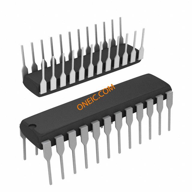
24-DIP
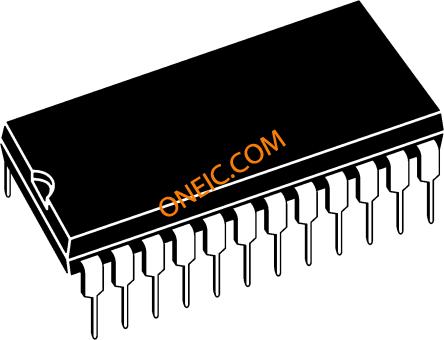
Image Preview
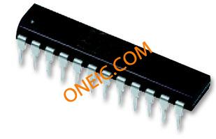
Image Preview