CD4051BPWR
Single 8-channel analog multiplexer/demultiplexer ICs in 16-pin TSSOP package
Manufacturer: ['rochester', 'ti']
series introduction
# CD4051BPWR Product Series Introduction
## 1. Overview
The CD4051BPWR belongs to a well - known family of analog multiplexers/demultiplexers. These integrated circuits are designed to perform the crucial function of selecting one of multiple input signals and routing it to a single output, or vice - versa in the case of demultiplexing. This product series is highly regarded in the electronics industry for its reliability, versatility, and cost - effectiveness, making it a popular choice for a wide range of applications.
## 2. Key Features
### 2.1. Wide Supply Voltage Range
The CD4051BPWR can operate over a broad supply voltage range, typically from 3V to 18V. This flexibility allows it to be used in various electronic systems with different power requirements. Whether it's a low - voltage battery - powered device or a higher - voltage industrial application, this multiplexer can adapt and function effectively.
### 2.2. Low On - Resistance
It features a relatively low on - resistance. When a particular input is selected and connected to the output, the low on - resistance ensures minimal signal attenuation and distortion. This is especially important for applications where accurate signal transfer is crucial, such as in audio and video signal routing.
### 2.3. High Channel Isolation
The product offers high channel isolation between the different input channels. This means that when one channel is selected and connected to the output, the other non - selected channels have very little interference with the selected signal. It helps in maintaining the integrity of the signal being routed and reduces cross - talk between channels.
### 2.4. CMOS Technology
Built using Complementary Metal - Oxide - Semiconductor (CMOS) technology, the CD4051BPWR consumes very low power. This makes it suitable for battery - operated devices where power efficiency is a key concern. Additionally, CMOS technology provides high input impedance, which minimizes the loading effect on the input signals.
### 2.5. Digital Control
The selection of the input channel is controlled by digital signals. It has three address inputs (A, B, C) that can be used to select one of the eight input channels. This digital control mechanism simplifies the integration of the multiplexer into digital systems and allows for easy programmability.
## 3. Pin Configuration
The CD4051BPWR comes in a standard 16 - pin package. Here is a brief description of the main pins:
- **Input Channels (X0 - X7)**: These are the eight analog input channels from which the desired signal can be selected.
- **Output Channel (Z)**: This is the single output pin where the selected input signal is routed.
- **Address Inputs (A, B, C)**: These three pins are used to select one of the eight input channels. The combination of logic levels on these pins determines which input is connected to the output.
- **Enable Input (INH)**: When this pin is set to a high logic level, the multiplexer is disabled, and the output is in a high - impedance state. When it is low, the multiplexer is enabled, and normal operation occurs.
- **Supply Pins (VDD, VSS)**: VDD is the positive supply voltage pin, and VSS is the ground pin.
## 4. Applications
### 4.1. Audio and Video Signal Routing
In audio and video systems, the CD4051BPWR can be used to select between different audio or video sources. For example, in a home theater system, it can be used to switch between different media players (such as a DVD player, a Blu - ray player, and a gaming console) and route the selected audio or video signal to the amplifier
Images for reference
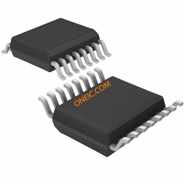
16-TSSOP

Image Preview
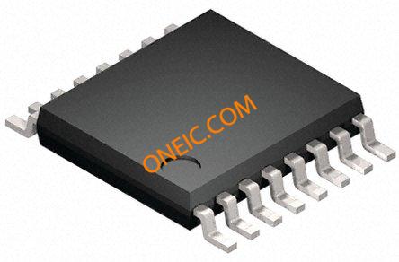
Image Preview