C1608X7R1H104K080AA
Compact 0.1uF ceramic capacitors for SMD applications, 50V, X7R dielectric
Manufacturer: tdk
series introduction
# Introduction to the C1608X7R1H104K080AA Product Series
## 1. Overview
The C1608X7R1H104K080AA product series belongs to the category of multilayer ceramic capacitors (MLCCs). These capacitors are essential passive electronic components widely used in various electronic circuits for functions such as filtering, decoupling, coupling, and energy storage. The specific model number contains a wealth of information about the capacitor's characteristics and specifications.
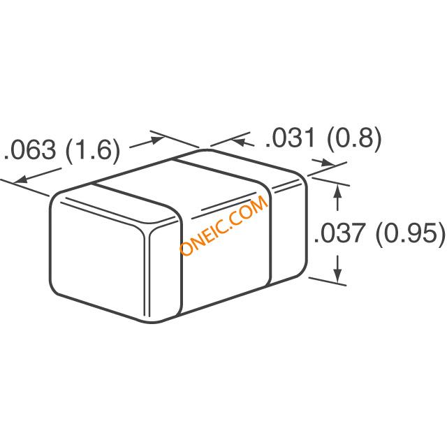
## 2. Physical Dimensions
The "1608" in the model number refers to the capacitor's size in the metric system. In this case, it has a length of 1.6 mm and a width of 0.8 mm. This compact size makes it suitable for use in printed circuit boards (PCBs) with high - density component placement, such as those found in mobile devices, wearables, and other miniaturized electronic products. The small form factor allows for more efficient use of board space, enabling designers to create smaller and more lightweight electronic devices.
## 3. Dielectric Material
The "X7R" indicates the type of dielectric material used in the capacitor. X7R is a Class II dielectric, which offers a good balance between capacitance stability and temperature coefficient. It has a relatively high dielectric constant, which means it can achieve a relatively large capacitance value in a small physical size. The temperature range for X7R dielectric is from - 55°C to +125°C, and within this temperature range, the capacitance change is limited to ±15%. This makes the C1608X7R1H104K080AA series suitable for applications where the operating temperature may vary, ensuring stable performance under different environmental conditions.
## 4. Voltage Rating
The "1H" in the model represents the voltage rating of the capacitor. In the standard capacitor coding system, "1H" corresponds to a voltage rating of 50V. This means that the capacitor can safely operate in circuits where the maximum voltage across it does not exceed 50V. It is important to select a capacitor with an appropriate voltage rating to prevent breakdown and ensure the long - term reliability of the circuit.
## 5. Capacitance Value
The "104" indicates the capacitance value of the capacitor. Using the standard capacitor coding convention, the first two digits (10) are the significant figures, and the third digit (4) is the multiplier. So, the capacitance value is calculated as 10 × 10⁴ pF, which is equal to 0.1 μF (since 1 μF = 10⁶ pF). This capacitance value is commonly used in a wide range of applications, such as power supply filtering to smooth out voltage fluctuations and in signal coupling circuits to transfer AC signals while blocking DC components.
## 6. Tolerance
The "K" represents the capacitance tolerance of the capacitor. A "K" tolerance means that the actual capacitance value of the capacitor can deviate from the nominal value (0.1 μF in this case) by ±10%. This tolerance is acceptable for many general - purpose applications. However, for more precise applications where a very accurate capacitance value is required, capacitors with tighter tolerances may be needed.
## 7. Packaging
The "080A" in the model number may be related to the packaging details of the capacitor. It could refer to a specific packaging style, such as tape - and - reel packaging, which is commonly used for automated surface - mount technology (SMT) assembly processes. Tape - and - reel packaging allows for efficient handling and placement of the capacitors on PCBs during mass production, reducing assembly time and cost.
## 8.
Images for reference

C SERIES_0603_0.95
-9.jpg)
C Series 0603(1608 Metric) 9
C SERIES_0603_0.95