C1005X7R1C103M
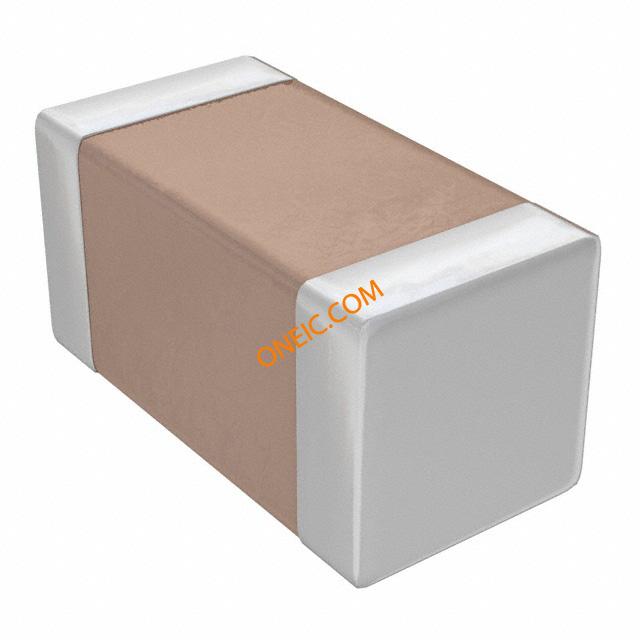
Compact multilayer ceramic capacitors for surface-mount applications
Manufacturer: tdk
series introduction
# Introduction to the C1005X7R1C103M Product Series
## 1. Overview
The C1005X7R1C103M product series belongs to the category of multilayer ceramic capacitors (MLCCs). These capacitors are essential passive electronic components widely used in various electronic circuits due to their excellent electrical properties, compact size, and high reliability. The naming convention of C1005X7R1C103M provides valuable information about the capacitor's key characteristics, which we will break down and explain in detail.
## 2. Naming Convention Analysis
- **C**: This typically indicates that the component is a capacitor.
- **1005**: Refers to the physical size of the capacitor, also known as the chip size. In the metric system, 1005 corresponds to a length of 1.0 mm and a width of 0.5 mm. This small form - factor makes it suitable for applications where space is limited, such as in mobile devices, wearable electronics, and miniaturized circuit boards.
- **X7R**: This is the dielectric type of the capacitor. X7R is a Class II dielectric, which offers a good balance between capacitance stability, temperature coefficient, and cost. It has a temperature range of -55°C to +125°C, and the capacitance change within this temperature range is limited to ±15%. This makes it suitable for a wide variety of applications where the operating temperature may vary.
- **1**: This digit often represents a specific voltage rating or other product - specific parameters. In some cases, it could be related to a standard voltage level within the series.
- **C**: This may be a manufacturer - specific code that could indicate additional features, such as a particular construction method or a specific performance grade.
- **103**: This is the capacitance value code. The first two digits (10) are the significant figures, and the third digit (3) is the multiplier. Using the formula \(C = \text{significant figures}\times10^{\text{multiplier}}\) (in picofarads), we get \(C=10\times10^{3}\text{ pF}=10000\text{ pF} = 10\text{ nF}\).
- **M**: This indicates the tolerance of the capacitance value. The letter 'M' represents a tolerance of ±20%. So, the actual capacitance of a C1005X7R1C103M capacitor can range from 8 nF to 12 nF.
## 3. Electrical Characteristics
### Capacitance
As mentioned above, the nominal capacitance of the C1005X7R1C103M capacitor is 10 nF with a tolerance of ±20%. This capacitance value is crucial for applications such as filtering, coupling, and bypassing in electronic circuits. For example, in a power supply filtering circuit, the capacitor helps to smooth out the DC voltage by storing and releasing electrical energy, reducing the ripple voltage.
### Voltage Rating
The voltage rating of the capacitor is an important parameter that determines the maximum voltage it can withstand without breaking down. While the naming convention does not explicitly state the voltage rating, it is typically specified in the product datasheet. Common voltage ratings for MLCCs of this size and type can range from a few volts to several tens of volts. For instance, if the voltage rating is 16 V, the capacitor can be safely used in circuits where the maximum voltage across it does not exceed 16 V.
### Temperature Coefficient
Thanks to the X7R dielectric, the C1005X7R1C103M capacitor has a relatively
Images for reference
C Series 0402
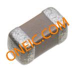
Image Preview